You are here
20 Meter Mult Stack
NR4M – The Goat Farm
This is an attempt to explain the whole story of this antenna from start to finish, so that readers might have a better idea of how it all works together. Building a high performance antenna system is not about any one thing, but many things, which all have to work correctly.
Construction began on the NR4M multi-multi contest station, also known as ‘The Goat Farm’, in the year 2000, and covers an area of 68 acres (24.8 hectares).
Because it is always more enjoyable to contest with others, it was decided to build the station for the needs of the multi operator category. With that in mind, the initial station configuration was for six stations, 10 m through 160 m. As time went along, it was determined that the developing contesting needs of the operators would require multiple radios on some bands. Sharing antennas and amplifiers on one band, between two radios, did not work out well. After installing separate antennas and amplifiers for EACH station on any one band, we had a system that worked well. Strategic placement of the second station antennas allowed two 1500 watt stations to operate on the same band without causing major interference problems. Typically, during a contest, the two stations are able to get within 3 to 4 KHz of each other, which is excellent!
So, now, with 2 radios and 2 amps on 40 m, 20 m and 15 m, things were much better and the stations’ scores and competitiveness was steadily improving.
The problem
In order to achieve maximum isolation between two radios on the same band, vertical 4 – squares arrays were chosen for the second (multiplier) station, while the primary station on each band would be using yagi antennas. The advantage of this is over 20 db of extra isolation achieved due to the difference in polarization, vertical vs horizontal, of the antennas used by the two stations.
Unfortunately, it did not take long to see a major disadvantage of this antenna strategy.
It was discovered that the current antenna system for the 'multiplier' station (in-band station) was not working as hoped for. It was fine and quite effective during the middle of the band opening, but was lacking in performance when the band was just OPENING or CLOSING.
The current 'multiplier' antenna for 20 meters consists of a ground mounted 4-square array of verticals. Each vertical has in excess of ninety, 1.5 mm copper radials under them. Also, they were installed as far away from the 20 meter 'run' antennas as could be managed. They are approximately ten wave lengths behind, and to the left, of the 'run' antennas, when facing Europe.
The real problem is that the typical four 4-square array has a take-off angle of about 28 degrees (according to EZNEC). Most experienced contest operators know that when the band is just opening, or closing, the required take-off angle for the signal is, generally, less than ten degrees! In practice, this meant that the second station operator, could call, and call, and call, just as the band was opening and get no response from the stations heard. Many times, the DX station would just be CQ'ing in the face of the NR4M OP!
Now, looking forward three or four hours and things were totally different. In the last Russian DX contest, worked at NR4M as a multi, hours after the band had opened to EU, DX stations commented on how LOUD the signal from NR4M was. These were the same stations that could not hear us at all earlier in the day.
It was obvious that the 'mult' station needed different (or additional) antennas to perform as needed.
The solution
After much discussion with others, it became apparent that the only good solution available was another tall stack of yagi antennas.
With that in mind, all options were considered for another yagi stack. A location was found that seemed promising, but it will not be known for sure, if it is too close to the other, existing 20 meter stack. That will have to wait until actual on-the-air testing is done.
About the same time, an opportunity arose to purchase a used rotating tower system that could not be refused. The purchase resulted in a very sturdy 160 foot (49 meter) tower with three rotary guy rings and a heavy duty base mounted rotator. This seemed like it would be the answer.
Unfortunately, for the previous three years, the guy bearing assemblies were left, upside down, exposed to the weather! This meant that ALL eighteen bearings assemblies had to be replaced.
Finally, after much work, the concrete anchors, the non metallic guys, and the tower were all in place. The tower was guyed at 50/100/150 feet (15/30/45 meters) which would allow the installation of three antennas, each just about a guy point. When the whole tower is rotating, it is most desirable to have the antennas ABOVE the guys than below them.
Now, it was time to design and build antennas.
The antennas
The antenna design software using in the past, had been shown to have some serious design flaws and produced a questionable model,. The search was ‘on’ for newer, and hopefully, better software. After reviewing advice from several respected sources, it was decided to purchase a license for NEC4. NEC4, which is the latest version of the NEC software engine, is used by many commercial and government customers. The latest version of the software EZNEC was also purchased to provide a user interface for NEC4. EZNEC is not the most 'user friendly, so a license for AutoEZ was also acquired. EZNEC gives the user accurate results based upon WHAT THE USER ENTERS. It does not give any indication on how to make the antenna any better; it just gives an 'output' based upon a specific 'input'. AutoEZ, on the other hand, is more of an 'automater' in that the user enters desired performance parameters, and AutoEZ will automatically run trial after trial, in order to attempt to achieve the desired results. Many times, this utility has run HUNDREDS of trials on a specific set of antenna parameters.
It took many months of trial, after trial to arrive at the final design for the new 'mult' antenna stack.
- 3 stack of 48 foot (14.6 meter) long, six element yagis.
- Operational bandwidth of 14.000 MHz to 14.150 MHz (NR4M does NOT do SSB!)
- Approximately 18.5 dbi gain, as a stack, over real earth conditions.
- 22 to 26 db front/back ratio over the intended operational bandwidth
- Less than 1.5:1 SWR from 14 MHz to 14.2 MHz
- “Hairpin' or Beta feed system centered on 14.050 MHz
Although not yet tested 'on-the-air' to verify that all desired parameters have met, months of extensive modeling have been encouraging.
Building the antennas
Being a retired machinist, the actual building of the antennas was not a problem and actually enjoyable. The shop at NR4M is equipped with all the metal working equipment needed for the job.
Many hundreds of feet of high strength aluminum tubing was purchased and cut into the lengths required for the designed taper schedule.
There was the choice of having the elements electrically connected and mounted directly to the boom, or have the elements electrically insulated from the boom. The electrically insulated method was chosen because there is a successful history of using that method in the past. It would have been fine either way.
In the past, non-metallic mounting plates made of linen phenolic (Garolite) have been used to attach the elements to the boom. It is not cheap, but it is very strong and weathers well. Garolite is made of linen fabric and resin, cured under heat and tons of pressure.
This build was going to be different. Aluminum structural channel was used to attach the elements to the boom. Mounted on the 4 inch x 12 inch (10.1 cm x 30.5 cm) aluminum channels are four plastic insulating bushings, which are sized to grip the tubing tightly and not create a slip fit. Each of the insulating bushings is held in place by a steel retaining plate and ¼ inch (6 mm) stainless steel bolts with lock nuts. In order to securely hold the aluminum channel to the 3 inch (7.6 cm) diameter, 1/8 inch (3 mm) aluminum boom, two hot dipped, galvanized U-bolt are used.
The feed method for this antenna build was a 'hairpin' or 'beta' match. See figure 1, below.
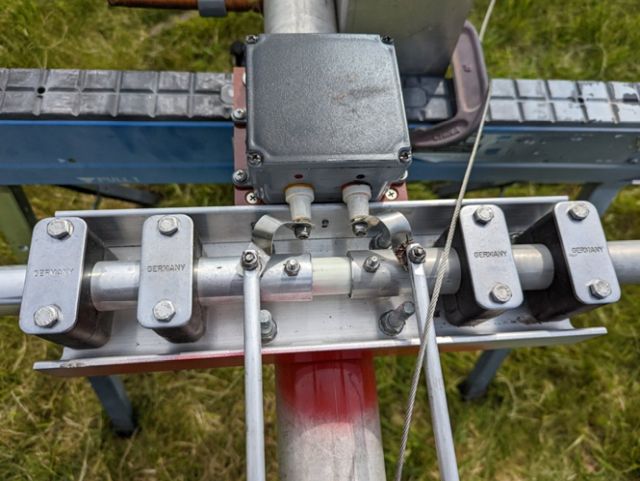
Figure 1. Feed point assembly
A hairpin uses a split driven element where each half of the driven element are separated by an insulator and has two parallel 'hairpin' rods attached, one to each driven element. The far end of these 'hairpin' rods are attached to the boom and are grounded for DC. By adjusting the tip lengths of the driven element and the position of a shorting bar on the 'hairpin', a match between the antenna feed impedance and the impedance of the feed line may be made. Grounding the far end of the hairpin rods (for DC) also helps reduce static on the driven element. (It is NOT grounded for RF). See figure 2, below
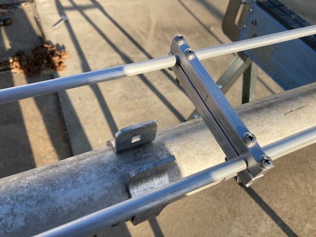
Figure 2. Adjustable shorting bar
The boom consists of two 24 foot (7.3 meter) pieces of high strength aluminum, 3 inches (7.6 cm) in diameter and 1/8 inch (3 mm) wall thickness. There is a 24 inch (61 cm) long, thick wall reinforcement sleeve at the joint to the two boom pieces. This also allows sufficient tightening of the boom to the tower without crushing the tubing.
Because the element spacing is not symmetrical, one end of the antenna is heavier than the other. To minimize any problems caused by imbalance, the light end of the boom has weight added internally to compensate. This is important when mounting the boom to the tower, as a boom that is tilted due to balance issues, is extremely difficult to easily get into the proper position. This can make for dangerous situations many feet up in the air!
All overlapped element sections are riveted in two places, with three rivets used at each location, spaced 120 degrees apart, for a total of 6 stainless steel rivets. These rivets are in both 1/8 inch and 3/16 inch (3 mm and 5 mm) sizes and must be installed with a special pneumatic tool.
With the exception of the driven element, all element tips are fastened with two, #8 stainless steel machine screws and nylon locknuts. The driven elements are secured with stainless steel compression clamps to allow for adjustment during tuning.
In order to properly support a 48 foot (14.6 meters) boom, two 3/16 inch (5 mm) stainless steel boom guys have been added. They attach approximately five feet (1.5 meters) from each end of the boom on one end, and on the other end, to a tower mounted bracket seven feet (2.1 meters) above the boom. Final adjustments are made with turnbuckles mounted to the tower bracket. See figure 3, below
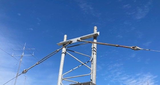
Figure 3. Adjustable boom guys bracket 7 feet above boom
Initially, each antenna is assembled on a large, concrete parking area in front of the garage. This allows for trial assembly, on a flat surface, in order to better assess the fit of all the custom manufactured parts.
The plate used to mount the antenna directly to the side of the tower, is 12 inches x 22 inches (30 cm x 56 cm) and 3/8 inch (10 mm) thick. There are eight set of holes for U-bolts holding the plate to the tower legs and seven sets of holes for holding the antenna boom to the plate. The plate is hot dipped galvanized and weighs about 40 pounds (18.1 kg)! See figure 4 below.
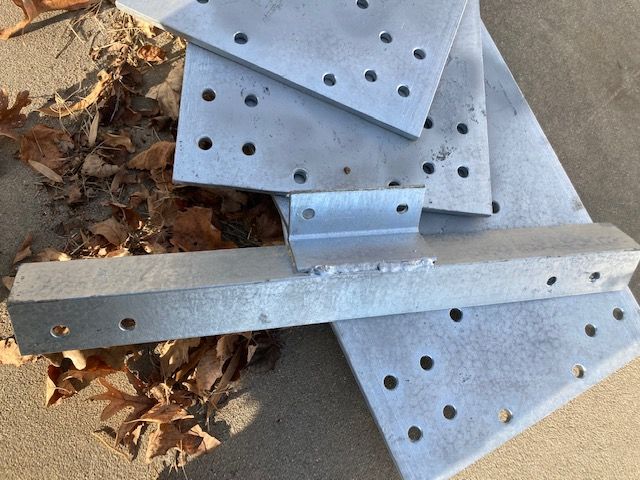
Figure 4. Boom mounting plates and boom guy brackets
After the trial fit, the elements are removed from the boom, the boom separated into two pieces and everything is moved to the near the tower,. Here, at the final location, it is all reassembled for the last time. All measurements are triple checked, by multiple people, and all bolts and other hardware checked, and rechecked.
As previously mentioned, the antenna feed system must be adjusted, in the field, before the antenna is permanently mounted. To that end, and based upon estimates, preliminary settings of the matching network are made. The antenna is then hoisted using 12 mm ropes, pulleys, and a strong diesel truck, to a height sufficient to offset the de-tuning effects of the ground.
Since the lowest antenna will be mounted at 50 feet (16.6 meters), that height was deemed sufficient.
It is really necessary to take measurements of the complex impedance of the feed point -at- the feed point. Unless there is someone willing to sit out on the antenna boom taking measurement, while high in the air, it is a difficult situation. However, there is a characteristic of coax feed line that is useful in testing situations like this.
A electrical half wave length of coax (492/Freq MHz x Velocity Factor = ½ wave coax in feet) will repeat the impedance of one end, to the other end. That is to say, if you have an electrical half wave length (or multiple ½ wavelengths) of coax, your testing equipment will show the same impedance values as if it were connected directly to the feed point, high in the air. In the case, of this antenna, we used three ½ wavelengths of RG-213 coax. This made the length of coax required, just over 65 feet (19.8 meters).
Measurements were made with a Rig Expert Antenna Analyzer, model AA-55
Using this method, it was easy to see exactly what effect our feed point changes would have.
This adjustment process did take a while. The antenna made 13 trips up/down the tower, but it was worth it. By the time the crew finished, and were more practiced, an impedance 49.5 ohms, -2.5j had been reached. This equates to an SWR of 1.05 @ 14.040 MHz. Not too bad!
A graph was not plotted, but notes showed the following bandwidth.
Freq MHz SWR
14.000 1.18
14.040 1.05
14.060 1.09
14.080 1.17
This is encouraging.
The preliminary settings for the next two antennas will be exactly where this testing session left off. It should only require one, maybe two, hoisting sessions to make sure all is well with the follow on antennas.
More about the overall system
There has been some interest in other aspects of this project.
Here is some additional information, in no particular order.
- The new tower is about 330 feet (100 m) from the shack. The coax from the shack to the tower base is 1 5/8 inch (4.1 cm) heliax. Attenuation appears to be about .24 db per 100m.
- The switch between any combination of the three antennas will be accomplished with a remote switch similar to either the Stack Match by Array solutions, or the one sold by the SJ2W contest team. This switch will be mounted at approximately 100 just above the middle antenna.
- From the ground up the 100 foot (30.4m) point, will either be 7/8 heliax, or ½ heliax, with attenuation specifications of .15 db/30m and .27 db/30m, respectively. Each antenna will be fed with a 71 feet (21.6m) piece of ½ heliax with attenuation of about .19 db/71 foot piece. So, that totals .24db + .15db + .19db = .6db.
- The balun used at the feedpoint is built as a current balun/common mode choke (balun.jpg). 12 turns of RG-400 Teflon coax wound on a 2.4 inch (6 cm) (FT240-31). Testing with a Vector Network Analyzer (VNA) show in excess of 3.5K ohms of impedance, mostly from series resistance (Rs) @ 14 MHz. This should work well.
- The copper straps from the balun to the feedpoint are not actually attached directly to the aluminum driven element. The machine screw is stainless steel (SS) and there are SS washers on both sides of the copper strap, so there should not an issue with galvanic corrosion. SS only touches the copper. (Stainless steel is an excellent interface between dissimilar metals in an antenna system.)
*Note on this: I, personally, have never seen a case of galvanic corrosion in connections like these when there was not sustained current flow thru the joints. On the other hand, I have seen severe galvanic corrosion in a receive vertical array, where small current was flowing thru the system continually for several months. (Power to the pre-amps: Down the coax to each antenna and then to ground via 3 foot (1m) ground rod. This was ~ 4 volts @ 70ma.) At, NR4M, many antennas have been up for decades, with this type of connection, and none have ever shown any type of corrosion. If there was not confidence in the longevity of my feeds, they surely would not be used. The copper strap (.4mm) was used because it was available in quantity.**
**4/1/2022 Change – Suitable aluminum material was found and the feed point connections were changed from copper to aluminum.